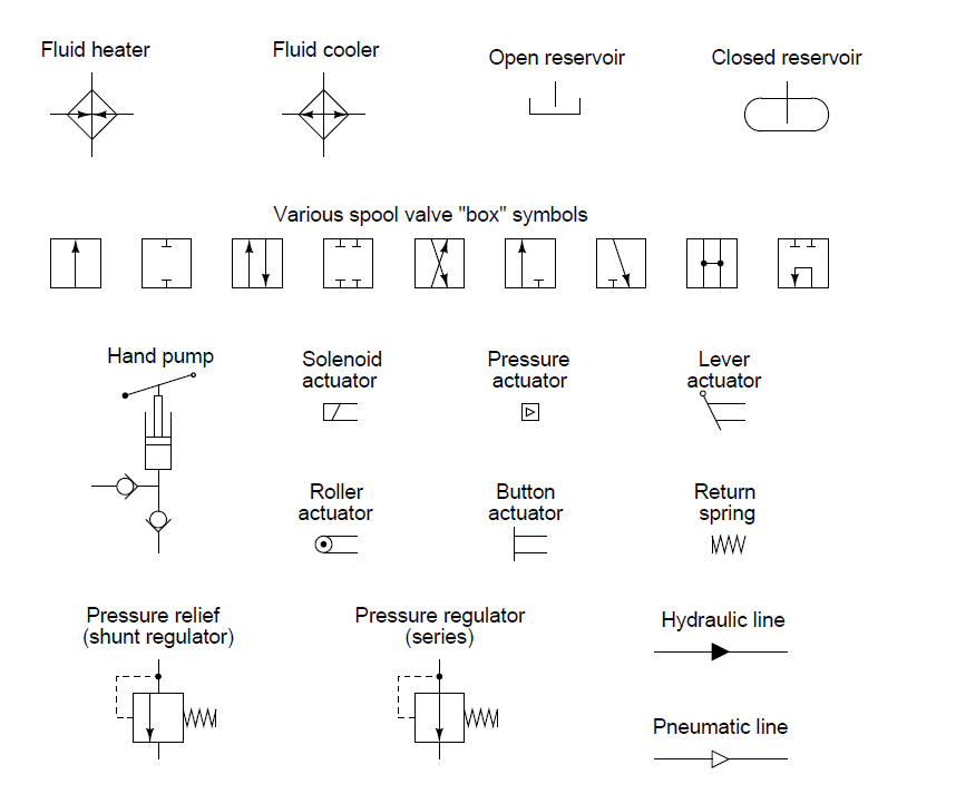
Fluid Power Schematic Symbols
Symbols fluid schematic power graphical hydraulic understanding drawings read used equipment air tennessee middle Hydraulic symbols basics fluid power components recognizing circuit basic elements below different controls technical identify Solved skill 7: (14 points) 2. your task is to design a
Fluid power graphic symbols
Fluid power formulas Industrial instrumentation and control: instrumentation and control symbols Fluid power graphic symbols
Fluid power symbols valve engineering figure diagrams doe
Fluid hydraulic power pneumatic line piping schematics symbols diagrams system pid figureFluid pressure reducing How to read a schematic, understanding of graphical symbols used inFluid symbols power used schematic understanding graphical drawings read hydraulic equipment air tennessee middle.
Fluid power symbols diagrams aeronautical hydraulics tpubSymbols fluid power ansi basic hydraulics iso pneumatics valves note Fluid power formulas – reasontek corpFluid symbols power schematic used read graphical understanding drawings.

Symbols control fluid diagram instrumentation power flow basics diagrams process systems
Schematic graphical understandingIso/ansi basic symbols for fluid power equipment and systems Formulas hydraulicHydraulic basics: recognizing hydraulic symbols.
Fluid power systemsHydraulic and pneumatic p&id diagrams and schematics Fluid power symbols solved transcribed text showIndustrial instrumentation and control: instrumentation and control symbols.

Fluid graphic
Symbols fluid power hydraulics ansi iso basic pneumatics equipmentReservoir symbols fluid power hydraulic pneumatic schematics diagrams pid figure Figure 4-5. fluid power diagram symbols.Fluid power graphic symbols.
Hydraulic and pneumatic p&id diagrams and schematicsMechanical symbols other than aeronautical for fluid power diagrams Fluid symbolFluid power symbols hydraulic schematic equipment diagram elements pneumatic flow actuator acting single rotary semi switch meter.

How to read a schematic, understanding of graphical symbols used in
Hydraulic and pneumatic p&id diagrams and schematicsDiagram power schematic fluid hydraulic pneumatic diagrams schematics system pid figure Design elementsSymbols fluid power diagram figure.
Fluid power formulasHow to read a schematic, understanding of graphical symbols used in Fluid power graphic symbolsSymbols fluid control power diagram instrumentation industrial.

Iso/ansi basic symbols for fluid power equipment and systems
Hydraulic circuitFluid piping How to read a schematic, understanding of graphical symbols used inFluid power symbols.
Fluid power graphic symbolsControl fluid power systems discrete symbols schematic system diagram components represent pumps fluids Symbols fluidHydraulic circuit of fluid power control system..

Figure 26 fluid power valve symbols
.
.


Fluid power graphic symbols

Fluid power graphic symbols
Industrial Instrumentation and Control: Instrumentation and Control Symbols

How to Read a Schematic, Understanding of Graphical Symbols Used in

Fluid Power Formulas - Reasontek Corp

Hydraulic circuit of fluid power control system. | Download Scientific